How to Choose the Best Milling Cutter Head?
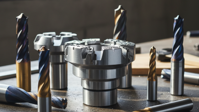
Choosing a Milling Cutter Head is not a catalog exercise. It is a decision about material, machine limits, surface finish, and tool stability. A cutter that looks suitable on paper may chatter against a thin workpiece or leave visible marks on a finished edge. Small details matter: spindle speed, holder runout, insert geometry, and coolant delivery can change the result.
Market reports show why this choice deserves careful attention. Grand View Research valued the global cutting tools market at USD 21.33 billion in 2023 and projected a 6.5% compound annual growth rate from 2024 to 2030. This broad market includes many tool types, not just milling heads, so the figure should be treated as context rather than a direct forecast for one product category. Still, it reflects continued investment in machining tools and production capability.
A reliable guide should connect that market context with practical selection criteria: workpiece material, cutter diameter, tooth count, cutting data, and the rigidity of the setup. It should also distinguish manufacturer specifications from independent performance evidence. I cannot verify a published, verbatim quotation from a named Milling Cutter Head specialist from the information provided, so I will not invent one. That limitation matters. A confident quote without a traceable source would weaken an otherwise useful guide.
Identify the Workpiece Material and Milling Operation
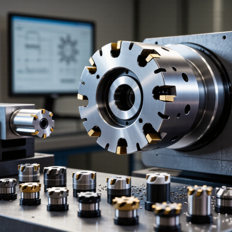
Identify the workpiece material before choosing a milling cutter head. Hardness is only part of the decision. Stainless steel can build heat and cling to an edge, while aluminum may form long, sticky chips. Cast iron is abrasive and produces fine dust. These differences affect cutting-edge geometry, grade, and coating. Small details matter. Check the material’s condition, too: a scaled surface or hardened skin can wear an edge faster than clean stock. If the exact alloy is unknown, treat published cutting data as a starting point, not a promise.
Match the head to the milling operation. Face milling needs stable support and suitable insert spacing; shoulder milling requires an edge that can control both the wall and floor. Slotting often traps chips, so flute space and chip evacuation become critical. For ramping or helical entry, confirm that the cutter head permits that approach. Chips tell a story. Long ribbons, built-up material, or a sudden rise in spindle load can signal a mismatch. I would check the machine’s rigidity and tool overhang before changing speed alone; that step is easy to overlook. A short test cut on representative stock can reveal chatter, poor finish, or excessive wear before the full job begins.
Check Machine Compatibility and Cutter Head Interface
Before choosing a milling cutter head, confirm the machine’s spindle interface, not just its advertised capacity. ISO 7388-1 defines a 7:24 steep-taper interface, while ISO 12164 specifies the HSK hollow-shank system with a 1:10 taper. These are not interchangeable. Check the spindle manual for the exact interface type and size, then compare it with the cutter-head drawing. Small mismatches matter. Also verify the retention method, gauge length, and maximum speed; a head that seats poorly can increase vibration and wear.
Check clearances on the actual machine. Measure the head’s diameter and length against the workpiece, fixture, and tool-change envelope. ISO 230-7 provides methods for assessing spindle-axis error motion, a useful reference when runout or finish quality is a concern. A test cut can reveal problems that a drawing misses. I would not trust a catalogue image alone. One detail is easy to overlook: coolant delivery may depend on the spindle and interface, so confirm the passage arrangement before ordering. Standards describe interfaces; they do not confirm your machine’s condition. Recheck the manual and, where uncertain, ask a qualified tooling technician to verify the fit.
Select Cutter Geometry, Substrate, and Coating
A milling cutter head should match the material, cut, and machine—not just the job’s nominal hardness. ISO 513:2012 divides cutting applications into six groups: P for steels, M for stainless steels, K for cast irons, N for non-ferrous materials, S for heat-resistant alloys and titanium, and H for hardened materials. Use this as a starting map, not a prescription. A sharp, positive-rake geometry can reduce cutting forces in aluminum; a tougher, stronger edge may better survive interrupted cuts in cast iron. Listen for chatter, too. The sound often reveals a poor geometry match before the edge looks damaged.
Substrate and coating must work together. Fine-grain carbide can support a sharp edge, while tougher grades can tolerate impact and vibration. PVD coatings are often chosen when edge sharpness matters; CVD coatings can suit applications needing a thicker wear barrier. ISO 8688-2:1989 sets out controlled face-milling tests for evaluating tool life, including wear assessment. Its test approach is a useful reminder: compare candidate heads under consistent feed, speed, and engagement, rather than relying on a catalogue claim. Record flank wear and finish. Small changes in overhang can distort the result. And, honestly, one trial is rarely enough; coolant delivery and workpiece variation can make a good choice look poor.
Match Cutter Size and Cutting Parameters to the Job
How to Choose the Best Milling Cutter Head?
Match cutter size and cutting parameters to the job. Start with the feature, not the catalogue. A 10 mm cutter may reach a narrow pocket, while a larger head can reduce deflection on a broad face. Check flute length, holder clearance, and spindle limits before setting speed. Cutter diameter also changes surface speed: at 6,000 rpm, a 10 mm cutter runs at about 188.5 m/min, using Vc = πDn/1,000. That is a calculation, not a universal recommendation; workpiece material and cutter construction matter.
Set feed per tooth alongside spindle speed. For a four-flute cutter at 0.04 mm per tooth and 6,000 rpm, the calculated feed is 960 mm/min. Then adjust for engagement, rigidity, and chip evacuation. ISO 8688-2:1989 provides standardized methods for milling tool-life testing, underscoring why comparisons need controlled cutting conditions. A setup that looks sound on paper can still chatter. Listen, inspect the chips, and make measured changes rather than raising every parameter at once.
Tips: Use the smallest cutter that safely reaches the feature, but avoid excessive stick-out. A short, thick tool is usually more stable. If chips smear or recut, check feed and coolant direction before changing the cutter head. Record the actual settings; one overlooked detail can make the next trial harder to interpret.
Compare Performance, Tool Life, and Replacement Costs
How to Choose the Best Milling Cutter Head?
A cutter head should be judged by the work it produces, not its purchase price alone. Compare cutting speed, surface finish, vibration, and how consistently it holds dimensions. On a steel workpiece, for example, inspect the edge and finish after a few repeat passes. A head that cuts quickly but leaves chatter marks may require slower settings or extra finishing.
Tool life depends on material, feed rate, setup rigidity, and heat. Record how many parts each head completes before wear affects quality. Then compare replacement costs, including inserts, downtime, and the labor needed to change or reset the tool. A lower-cost option can become expensive if it needs frequent attention. No test is perfect; small differences in setup can distort the results.
Tips: Test candidate heads on the same material and machine settings. Track usable parts per edge, not just cutting hours. Check replacement time, too. It is easy to overlook. If results vary, repeat the test before choosing; a neat spreadsheet cannot fix an inconsistent setup.