Why Are Tool Holders Important for CNC Machining?
Tool Holders are more than adapters between a CNC spindle and a cutting tool. They help determine how accurately the tool runs, how firmly it stays seated, and how reliably cutting forces reach the workpiece. In practice, a few microns of runout can leave visible marks on a finished surface. Vibration can also shorten tool life and disrupt a carefully planned cycle.
The technical basis is clear. ISO 26623 specifies polygonal taper interfaces, while ISO 230-1 sets out methods for testing machine-tool accuracy. These standards do not promise a particular machining result. They give manufacturers shared reference points for evaluating interfaces and machine performance. AMT’s U.S. Manufacturing Technology Orders reports provide another useful industry signal: they track machine-tool orders and investment, reminding shops that dependable results depend on the full machining system—not the machine alone.
A practical expert takeaway, paraphrased rather than presented as a verbatim quotation, reflects precision-machining principles associated with Dr. Scott Smith, a manufacturing and precision-engineering specialist: “A spindle can only deliver the accuracy its tool interface preserves.” That distinction matters on the shop floor. A clean, correctly matched holder supports repeatable setup; a worn or poorly balanced one can undermine it. Small component. Big consequences.
This introduction examines why Tool Holders deserve attention when shops select cutters, manage vibration, and protect surface quality. It also leaves room for a useful caution: holder choice cannot compensate for every setup error. The spindle, tool, workholding, and cutting conditions still have to work together.
What Is a Tool Holder in CNC Machining?
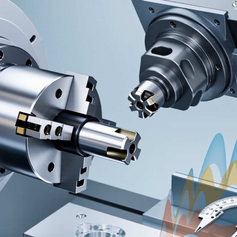
A tool holder is the mechanical link between a CNC machine’s spindle and its cutting tool. It grips the tool, locates it on the spindle axis, and transfers torque during cutting. Common interfaces use a tapered shank and a retention feature; the holder’s front end may use a collet, hydraulic chamber, or precision bore. In practice, a tiny chip on the taper can prevent full contact. The result may be vibration, poor surface finish, or uneven tool wear.
A holder also affects runout, balance, and tool-change repeatability. ISO 21940-11:2016 defines balance-quality grades, including G2.5, for rigid rotors; the right grade depends on speed and the complete rotating assembly. It is not a universal setting for every tool holder. ISO 7388-1:2007 specifies dimensions for one common spindle-interface family, helping manufacturers maintain compatible connections. Still, standards cannot compensate for a worn taper or a loose clamping mechanism. Those details are easy to overlook.
Tips: Wipe the spindle and holder taper before installation. Check runout near the cutting edge, not only at the holder nose. Keep records of vibration and tool life; patterns can reveal a problem before the finish does. And do not assume a clean-looking holder is accurate.
How Does a Tool Holder Secure and Position a Cutting Tool?
A tool holder connects the spindle to the cutting tool and keeps the tool aligned during machining. Its taper or interface seats against the spindle, while a collet, chuck, or other clamping system grips the tool shank. The contact surfaces matter. A small chip trapped on a taper can tilt the holder and create runout, even when the tool feels firmly clamped.
The holder also controls how far the cutting edge extends from the spindle. That distance affects clearance, stiffness, and vibration. Keep the tool projection as short as the job allows. Too much overhang can make a cut chatter, leaving ripples on a finished surface. Still, a secure grip alone does not guarantee accurate positioning. Check the holder’s condition, clean the mating surfaces, and confirm the tool sits at the intended gauge length. It is easy to assume a setup is sound because it looks right; measurement can tell a less comfortable story.
Tips: Clean the spindle and holder before assembly. Tighten the clamp to its specified method, then check runout near the cutting edge. If vibration persists, inspect tool projection and balance before changing cutting settings. A quick check saves rework.
Which Machining Factors Depend on Tool Holder Performance?
Tool-holder performance shapes more than tool retention. It affects runout, vibration, heat transfer, and the cutting edge’s stability. ISO 230-7:2015 specifies measurement of spindle error motion, including radial and axial components. These measurements matter because a holder adds another interface between spindle and cutter. Even small deviations can make one flute carry more load than the others. The result may be uneven wear, chatter marks, or a finish that varies across the part.
It also affects accuracy. A rigid, well-seated holder helps keep the cutter on its programmed path, especially during long-reach milling. Vibration data can expose problems that a visual inspection misses. ISO 20816-1:2016 provides a framework for evaluating machine vibration, though its limits depend on machine type and operating conditions. Check runout near the cutting edge, not only at the holder nose. Small detail, big difference. A clean taper and correct clamping force help prevent movement under load, but neither can fix a worn spindle interface. In practice, holder choice should match tool length, cutting force, and material. There is no universal “best” holder; shop measurements may challenge assumptions made from a catalogue.
What Are the Main Types of CNC Tool Holders?
CNC tool holders form the connection between the spindle and the cutter. Their interface must match the machine: CAT and BT holders use steep tapers, while HSK holders use a hollow taper and face contact. HSK designs are often chosen for high-speed work because they provide strong contact at the spindle face. Check the machine specification; similar-looking tapers are not automatically interchangeable.
The gripping style matters just as much. Collet holders suit varied shank sizes and quick tool changes, making them useful for drills and smaller end mills. Side-lock end-mill holders grip a cutter’s flat firmly, but may offer less concentric accuracy. Hydraulic holders use internal fluid pressure for even clamping. Shrink-fit holders heat the holder for tool insertion, then contract around the shank. Shell-mill holders support larger face cutters with a central arbor and drive keys. Fit matters.
A practical choice depends on cutter diameter, cutting load, spindle speed, and required runout. For a small finishing tool, low runout can improve the surface; for heavy roughing, rigidity and torque transfer may matter more. Keep the gauge length short where possible, and check balance at higher speeds. Chips or wear inside a holder can spoil accuracy. This detail is easy to overlook. Even a good holder cannot compensate for a damaged collet or a poorly matched spindle interface.
Why Tool Holders Matter: Main CNC Tool Holder Types
A tool holder connects the cutting tool to the machine spindle. The right holder helps provide secure clamping and suitable performance for the operation.
Typical application fit is a qualitative comparison, not a measured industry statistic. ER collet holders are versatile; milling chucks and side-lock holders suit many end-milling tasks; hydraulic and shrink-fit holders are often chosen for precision work; shell-mill arbors hold face mills.
How Should Tool Holders Be Selected and Maintained?
Selecting a tool holder starts with the operation, not the catalog. Match its interface to the machine spindle, then check the cutter shank diameter, gauge length, and required reach. For roughing, prioritize rigidity; for a small finishing tool, balance and runout matter more. A long holder may clear a fixture, but it can also increase deflection. Details matter.
Check the holder’s speed rating against the planned spindle speed, and confirm that coolant delivery suits the tool and operation. Measure runout near the cutting edge with a clean indicator. Even a few microns can affect finish and tool life. Keep mating tapers and contact surfaces clean and free of nicks. A trapped chip can prevent proper seating. Easy to miss.
After use, wipe and inspect holders for fretting, corrosion, cracks, or damaged drive features. Store them in protective racks. Clean collet slots and nuts carefully, and replace worn components rather than tightening harder. Track vibration, noise, and surface finish as clues, not proof of a holder fault. I have seen a holder blamed when a worn spindle was the real cause; that diagnosis deserves a second look. When wear is uncertain, ask a qualified technician to inspect the holder. Retire damaged units.