

How to Choose the Right Threaded Linear Shaft?
Choosing a Threaded Linear Shaft starts with the movement it must deliver, not simply the shaft’s diameter. A compact actuator moving a light sensor has different needs from a machine positioning a loaded carriage throughout a work shift. Thread pitch affects travel per rotation, while shaft diameter, unsupported length, and support spacing influence stiffness and deflection. Small mismatches can lead to vibration, uneven motion, or premature wear.
Start by defining the load, travel distance, speed, duty cycle, and positioning accuracy. Check these requirements against manufacturer load and speed ratings, including how the shaft is supported. Then consider material, thread form, nut compatibility, lubrication, and exposure to dust or moisture. A shaft that performs well in a clean test setup may behave differently near abrasive debris or frequent washdowns. Details matter.
There is no single specification that suits every machine. Higher accuracy may add cost, and a thicker shaft may need more installation space. Those trade-offs deserve a second look. Compare the product data with the actual operating conditions, and confirm critical dimensions before ordering. This guide explains the main selection factors, common mistakes, and practical checks for matching a threaded shaft to its application. Real installations can still reveal surprises, so leave room to inspect, adjust, and verify performance after assembly.
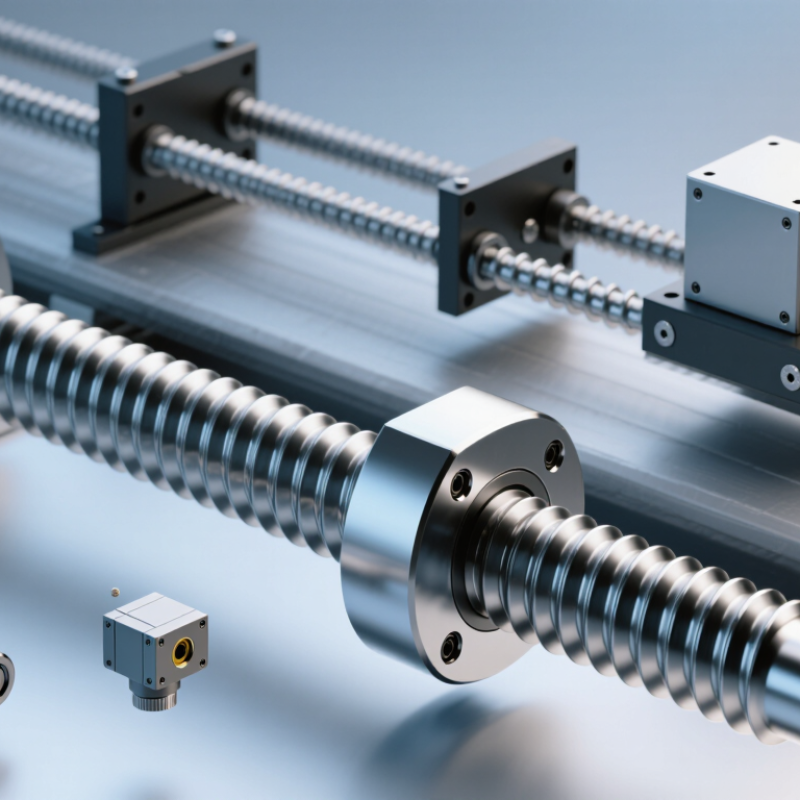
Identify the Motion and Load Requirements
A threaded linear shaft should match the motion it must produce, not just fit the available space. Define the required stroke, travel speed, and positioning accuracy before choosing a thread. A short, slow adjustment has different needs from a carriage moving repeatedly across a long rail. Small details matter.
Record the load in each direction, including the weight of the moving parts and any force applied during operation. For a vertical shaft, the screw may need to lift the load and resist its tendency to descend. For a horizontal assembly, misalignment can add friction and uneven wear. Note whether the load is steady or changes suddenly. Peak forces are easy to overlook.
Then consider the duty cycle: how often the shaft moves, how long it runs, and how much time it rests. A fast lead can increase travel per rotation, but it may require more torque and make fine positioning harder. Check the shaft’s unsupported length and support points, especially under compression, where bending or buckling may become a concern. Measure it twice. If the load or motion is uncertain, test the real assembly at a modest speed before settling on a specification. That test may reveal vibration, backlash, or friction that a drawing does not show.
Choose the Shaft Diameter, Length, and Material
A threaded linear shaft should be sized for the loads and support it will actually see. Diameter affects stiffness, not just strength. A long shaft with an unsupported middle can deflect or vibrate, even when the applied load seems modest. Check the load, shaft span, bearing arrangement, and thread dimensions together. If the shaft moves vertically, consider buckling as well. A quick calculation helps, but confirm assumptions against the machine’s duty cycle.
Length needs more thought than adding the required travel. Allow room for the nut, end supports, coupling, and any travel limits. For example, a 500 mm travel may require a shaft longer than 500 mm, depending on the assembly. Measure the usable threaded section and the overall length separately. Small oversights here can make installation awkward.
Choose material for the environment and contact conditions. Alloy steel can suit higher loads, while stainless steel may be useful where moisture is present; its strength and wear behavior still need checking. Consider surface finish, corrosion exposure, lubrication, and nut material together. There is no universal best choice. A clean workshop and a washdown area ask different things of the same shaft. I would verify the final dimensions with the shaft supplier or a qualified designer, especially when the span is long or the load changes direction.
How to Choose the Right Threaded Linear Shaft
Shaft diameter has a strong effect on stiffness. This comparison shows the calculated mid-span deflection for solid steel shafts under the same load and span.
Illustrative elastic-beam calculation: simply supported shaft, 500 mm span, 100 N center load, and steel with an assumed Young’s modulus of 200 GPa. Deflection is calculated using nominal diameter and a solid circular cross-section. For a threaded shaft, use the thread-root diameter for sizing; also check length, material strength, support conditions, buckling, and operating loads.
Match the Thread Type, Pitch, and Lead
Choose the thread form to match the load, movement, and mating nut. Trapezoidal threads are common in power transmission because their angled flanks support axial loads. Acme threads use a similar profile, but dimensions and standards differ, so they are not automatically interchangeable. For a fine-positioning stage, a finer pitch can provide smaller movement per turn. For heavier loads or faster travel, a coarser thread may be more suitable. Check the nut specification, not just the shaft diameter. Small details matter.
Pitch is the distance between neighboring thread crests. Lead is how far the nut travels in one shaft revolution. On a single-start thread, pitch and lead are equal. On a multi-start thread, lead equals pitch multiplied by the number of starts. For example, a 2 mm pitch, two-start shaft advances 4 mm per turn. This distinction is easy to miss when comparing catalog dimensions. It can lead to unexpected travel speed or positioning resolution.
Before ordering, compare the thread form, nominal diameter, pitch, lead, and tolerance with the nut and assembly drawing. A caliper can help check diameter, but it cannot reliably identify every thread detail. Use a thread gauge or verified technical drawing where possible. Consider backlash, lubrication, and the operating load, too. A faster lead may reduce travel time, but it can also change the force and control required. The best choice is not always obvious; test the complete shaft-and-nut combination when precision matters.
| Thread type or example | Pitch and lead | Typical characteristics | A suitable choice when… | Check before ordering |
|---|---|---|---|---|
| Metric trapezoidal thread, Tr 16 × 4, single-start | 4 mm pitch; 4 mm lead per revolution | Power-transmission thread with a 30° included thread angle under the ISO metric trapezoidal system. | You need a Metric Lead Screw for general linear movement and want a straightforward relationship between rotation and travel. | Confirm the nut uses the same nominal diameter, pitch, hand, and thread standard. |
| Acme thread, 10 TPI, single-start | 0.100 in pitch; 0.100 in lead per revolution | Inch-based power-transmission thread with a 29° included thread angle. | Your design uses inch dimensions and requires a commonly used screw-thread form for linear motion. | Check the nominal diameter, number of threads per inch (TPI), thread hand, and matching nut specification. |
| Acme thread, 10 TPI, two-start | 0.100 in pitch; 0.200 in lead per revolution | Two starts increase travel per revolution while retaining the stated spacing between adjacent thread forms. | You need more travel per motor revolution than a single-start thread of the same pitch. | Specify the number of starts and lead explicitly; pitch alone does not define travel per revolution on a multi-start thread. |
| Metric ISO coarse thread, M10 × 1.5, single-start | 1.5 mm pitch; 1.5 mm lead per revolution | Standard metric fastening thread; it is not automatically a power screw or a precision linear-motion thread. | The shaft is mainly intended for fastening or adjustment, and the application is compatible with a fastening-thread profile. | For repeated motion or load transmission, verify wear, backlash, lubrication, and nut suitability; consider a trapezoidal or Acme thread instead. |
| Fine-pitch metric thread, M10 × 1.0, single-start | 1.0 mm pitch; 1.0 mm lead per revolution | Smaller travel per revolution than an M10 × 1.5 single-start thread; commonly used where fine adjustment or fastening requirements call for it. | You need smaller axial movement per turn in a compatible fine-thread application. | Confirm the mating thread is also M10 × 1.0; fine and coarse pitches of the same diameter are not interchangeable. |
| Multi-start trapezoidal thread | Lead = pitch × number of starts | Provides greater linear travel per revolution than a single-start thread with the same pitch. | Higher travel per revolution is important and the drive, load, and positioning requirements suit the resulting lead. | Request both pitch and lead, plus the start count. Do not use pitch alone to calculate travel per revolution. |
Selection rule: Pitch is the distance between adjacent thread forms. Lead is the axial distance the shaft advances in one revolution. For a single-start thread, lead equals pitch; for a multi-start thread, lead equals pitch multiplied by the number of starts. Always match the shaft and nut thread form, nominal size, pitch, lead or start count, hand, and applicable standard.
Check Speed, Alignment, and Operating Conditions
How to Choose the Right Threaded Linear Shaft?
Check Speed, Alignment, and Operating Conditions
Choose a shaft for its actual duty cycle, not its advertised maximum speed. Record travel speed, stroke length, load, and starts per hour. A shaft moving a light carriage intermittently faces different demands from one carrying a heavy fixture continuously. ISO 281:2007 defines bearing basic rating life, L10, at 90% reliability under stated conditions. This applies to rolling bearings, not the shaft itself, but it helps assess the support assembly.
Alignment matters just as much. A small mismatch between the shaft, nut, and bearing supports can cause uneven contact, vibration, heat, and early wear. Check mounting faces and parallelism during installation; a dial indicator can reveal runout that is hard to spot by eye. Dust, coolant, temperature swings, and poor lubrication also change performance. I would not assume a clean workshop test predicts a production line perfectly.
Tips: Mark the shaft’s travel path, measure temperature after a full operating cycle, and listen for new clicking or scraping. Recheck alignment after mounting bolts are tightened. Keep a little doubt in the specification: real loads and installation conditions can differ from estimates.
Verify Component Compatibility and Manufacturing Quality
Choose a threaded linear shaft as part of an assembly, not as an isolated part. Match its nominal diameter, thread form, pitch, and lead to the nut and drive system. Confirm the thread’s direction and usable travel, too. A nut that turns onto the shaft is not proof of compatibility. Not enough.
Check how the shaft meets its bearings, couplers, and mounting blocks. Small differences in shoulder position or end machining can prevent proper alignment. Ask for material specifications and inspection records covering diameter, straightness, and thread dimensions. A dial indicator can reveal runout during a practical assembly check. Inspect the thread crests and roots for burrs, uneven machining, or damage. Surface finish matters, but a shiny surface alone does not establish quality. It is easy to focus on the thread and overlook shaft straightness. I would verify the complete part drawing against the actual mating components, then test movement across the required travel. If the load or operating conditions are uncertain, document that uncertainty before approving the shaft.

