
How to Choose Indexable Milling Cutters in 2026?

Choosing Indexable Milling Cutters in 2026 requires more than comparing prices, flute counts, or catalog photographs. Modern workshops face tougher alloys, tighter tolerances, and rising energy costs. Digital tool monitoring also changes how cutters are selected and evaluated. A cutter must match the machine, material, workholding, and cutting strategy.

Machining dynamics researcher Tony Schmitz offers a practical principle: “A stable cut comes before a fast cut.” That idea remains highly relevant. An aggressive cutter can look impressive during a short trial, then produce chatter, damaged inserts, or a poor surface finish. The sound of vibration matters. So does the thin curl leaving the workpiece. These details often reveal more than a sales chart.

This guide examines how to compare Indexable Milling Cutters for real production conditions. It considers insert geometry, grade, rake angle, cutter diameter, runout, coolant delivery, and chip evacuation. It also explains why one cutter may perform well in stainless steel but struggle in hardened tool steel. Some recommendations will seem obvious. Others may challenge common shop habits.

There is no perfect selection formula. Even experienced machinists make wrong assumptions. A catalog rating cannot replace a controlled test. Start with conservative cutting data, inspect the insert edges, and record spindle load, noise, tool life, and surface quality. Then adjust one variable at a time. Small mistakes remain useful when the process captures them. That discipline creates a more reliable path toward productive milling in 2026.
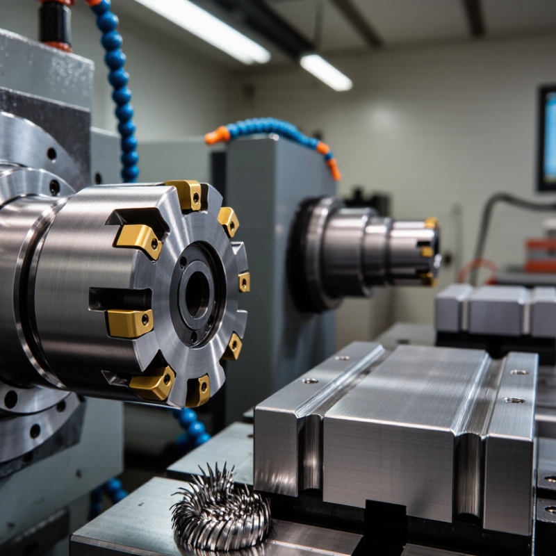
How to Choose Indexable Milling Cutters in 2026?

What Indexable Milling Cutters Are and How They Work

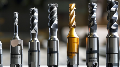
Indexable milling cutters use replaceable inserts instead of permanent cutting edges. The cutter body holds each insert in a precise pocket. When one edge becomes dull, the operator loosens the screw, rotates the insert, and exposes a fresh edge. This process reduces setup time and avoids replacing the entire tool. It also creates predictable cutting behavior when the inserts are seated correctly.

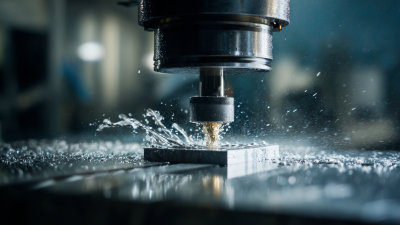
During rotation, each insert enters the workpiece, removes a chip, and exits before the next insert engages. Insert geometry controls how this happens. Positive rake angles reduce cutting force, while stronger negative geometries tolerate heavier cuts. Chip breakers guide chips away from the cutting zone. That sound matters. A sharp, stable cut usually produces a steady tone, while irregular noise can indicate runout, vibration, or poor clamping.

Choosing cutters in 2026 requires more than comparing catalog dimensions. Match the insert material and coating to the workpiece, cutting speed, coolant method, and machine rigidity. More flutes can disappoint. They may increase productivity, but insufficient chip space can cause recutting and heat. I have learned to check spindle runout, insert seating, and screw torque before judging a cutter. A small seating error can damage an expensive workpiece quickly. Manufacturer data provides a reliable starting point, but test cuts still deserve attention. My own first setting is rarely perfect. Feed, depth, and coolant often need adjustment after observing chip shape and edge wear.

How to Match Cutter Types with Milling Operations

How to Choose Indexable Milling Cutters in 2026?

Match the cutter to the operation, not only the material. For broad, flat surfaces, an indexable face mill removes stock efficiently. A 45-degree lead angle usually reduces cutting pressure and leaves a smoother entry. Use a 90-degree shoulder mill when the part needs a sharp vertical wall. For deep pockets, choose a cutter with generous chip space. Crowded flutes can trap chips and damage the pocket.

Slotting demands another decision. A full-width cut creates heavy radial force, especially in stainless steel or titanium. Fewer teeth and stronger inserts may protect a less rigid machine. High-feed cutters suit shallow axial depths and large table movements. They can shorten roughing time, but they are poor choices for deep shoulders. Finishing often benefits from wiper inserts and stable radial engagement. Small details matter.

Deloitte’s 2024 Smart Manufacturing and Operations Survey found that 86% of manufacturers consider smart manufacturing important. That supports tracking spindle load, tool life, and insert changes during production. USCTI and Oxford Economics reported U.S. cutting-tool consumption at approximately 2.6 billion dollars in 2024, showing the scale of tooling decisions. Still, a report cannot select your cutter. Measure the machine’s power, holder runout, coolant delivery, and workholding first. I have seen an excellent cutter fail because the fixture flexed. The imperfect choice is sometimes the useful one: test a stable insert grade, record the result, then revise the selection.

How to Select Inserts, Grades, and Cutting Geometries

Choosing indexable milling cutters in 2026 starts with the insert, not the cutter body. Match the insert shape to the operation and available clearance. A positive geometry reduces cutting force and suits thin walls or weaker machines. A stronger negative geometry handles heavy roughing and interrupted cuts. Sharp edges cut freely, but they can chip when vibration appears.

Grade selection should follow the workpiece, coolant, and cutting temperature. A tougher grade is safer for interrupted cuts, cast surfaces, and unstable setups. A harder wear-resistant grade can perform better during continuous machining of abrasive alloys. Do not select by material name alone. Check hardness, scale, and actual chip formation at the machine. A short trial cut often reveals more than a chart.

Chipbreaker design also matters. Choose a light cutting chipbreaker for finishing and a stronger one for deeper engagement. Keep the insert corner radius proportional to wall thickness and feed rate. A large radius improves edge strength, yet it may increase cutting pressure. Watch spindle load, sound, burrs, and flank wear after several passes. I sometimes choose a conservative grade first, then adjust it after measuring wear. That choice is not always optimal. Real setups are rarely as stable as the calculation suggests. Fresh coolant helps, but it cannot fix poor workholding or excessive runout.

How to Choose Indexable Milling Cutters in 2026? — How to Select Inserts, Grades, and Cutting Geometries
Practical starting recommendations for selecting indexable milling inserts. Actual parameters must be adjusted for cutter diameter, machine rigidity, tool overhang, coolant, workholding, and insert manufacturer's certified data.
Workpiece Group Typical Materials Recommended Insert Grade Cutting Geometry Edge Preparation Starting Cutting Speed
(Vc)
Feed per Tooth
(fz)
Recommended Use
ISO P
Low- to Medium-Carbon Steel
Low-carbon steel, structural steel, alloy steel below approximately 30 HRC Tough coated carbide
P20–P35 application range
Positive or semi-positive rake;
medium chipbreaker with open chip space
Small honed edge, approximately 0.02–0.05 mm 120–220 m/min 0.08–0.25 mm/tooth General face milling, shoulder milling, and slotting with stable workholding
ISO P
Hardened Steel
Tool steel and alloy steel approximately 45–60 HRC Hard-milling carbide or ceramic
P/H45–H55 application range
Strong cutting edge;
negative or neutral microgeometry for interrupted cuts
Reinforced hone or chamfered edge 60–160 m/min 0.03–0.12 mm/tooth Finishing and light roughing; use rigid setups and avoid excessive radial engagement
ISO M
Stainless Steel
Austenitic, ferritic, and martensitic stainless steels Tough, sharp coated carbide
M20–M35 application range
Highly positive rake;
polished or high-clearance chipbreaker to reduce work hardening
Sharp edge or light hone, approximately 0.01–0.03 mm 80–180 m/min 0.05–0.20 mm/tooth Use constant tool engagement, adequate chip evacuation, and avoid dwelling in the cut
ISO K
Cast Iron
Gray cast iron, ductile iron, compacted graphite iron Wear-resistant coated carbide
K10–K25 application range
Neutral or slightly positive rake;
stable edge for abrasive chips
Light hone or chamfer for interrupted cutting 100–250 m/min 0.08–0.30 mm/tooth Dry cutting is often suitable; use dust extraction and protect machine ways
ISO N
Aluminum and Non-Ferrous Metals
Wrought aluminum, cast aluminum, copper alloys, brass Uncoated polished carbide or PCD
N05–N15 application range
Very positive rake;
large polished flute and high chip clearance
Extremely sharp edge; avoid excessive honing 300–1,500 m/min 0.08–0.35 mm/tooth High-speed face or high-feed milling; use air blast or coolant to prevent chip welding
ISO S
Titanium Alloys
Titanium alloys and heat-resistant titanium grades Tough heat-resistant coated carbide
S15–S25 application range
Positive variable helix;
low-rubbing geometry with strong edge support
Small hone, approximately 0.02–0.05 mm 30–80 m/min 0.04–0.15 mm/tooth Maintain continuous chip load; use high-pressure coolant and avoid heat accumulation
ISO S
Nickel-Based Superalloys
Nickel-based heat-resistant alloys and cobalt-based alloys Highly wear-resistant tough carbide
S20–S35 application range
Positive rake with a reinforced edge;
chip-thinning geometry for lower cutting forces
Reinforced hone, approximately 0.03–0.06 mm 20–60 m/min 0.03–0.12 mm/tooth Prefer shallow radial engagement, stable feed, and high-pressure coolant
ISO H
Hardened Materials
Hardened tool steel, bearing steel, hardened die steel above approximately 45 HRC Fine-grain carbide, ceramic, or CBN
H10–H25 application range
Neutral to negative rake;
strong edge designed for hard milling
Chamfered or honed edge for impact resistance 40–180 m/min 0.02–0.10 mm/tooth Use rigid machines, short tool overhang, and light radial engagement for finishing
General Selection
Face Milling
Most steels, stainless steels, and cast irons Coated carbide with 4–8 cutting edges
Select grade by workpiece group
Positive lead angle and chip-thinning geometry;
wiper insert for improved surface finish
Match edge strength to interruption and machine rigidity 80–250 m/min 0.06–0.25 mm/tooth Choose cutter diameter so that approximately 50–75% of the cutter is engaged in the workpiece width
General Selection
Shoulder and Slot Milling
Steel, stainless steel, cast iron, and non-ferrous alloys Tough carbide with secure insert seating
Use stronger grades for interrupted cuts
Variable helix or differential pitch;
positive geometry for lower cutting forces
Use a reinforced edge for full-slotting or interrupted cuts 60–180 m/min 0.04–0.18 mm/tooth Reduce radial depth of cut when vibration occurs; check insert screw and pocket cleanliness
Parameter reference: Cutting speed is the surface speed at the insert edge. Feed per tooth is the programmed feed divided by spindle speed and the number of effective teeth. For a first trial, begin near the lower end of the stated range, verify chip formation and spindle load, then increase speed or feed progressively. For cutter diameter D and cutting speed Vc, spindle speed can be estimated as n = 1,000 × Vc ÷ (π × D).

How to Compare Tool Materials, Coatings, and Cutter Sizes

How to Choose Indexable Milling Cutters in 2026?

Tool material should match the workpiece, cutting speed, and machine stability. Cemented carbide remains the practical baseline for steel and stainless steel. Cermet can improve finish on stable, continuous cuts, while ceramic handles high-temperature alloys but dislikes interrupted engagement. For aluminum, polished carbide or polycrystalline diamond can reduce built-up edge. The 2024 USGS Mineral Commodity Summaries reported approximately 81,000 metric tons of global tungsten mine production in 2023. That figure matters because tungsten supply influences carbide cost and availability.

Coatings deserve a closer comparison. Titanium aluminum nitride suits hotter cutting conditions, while aluminum chromium nitride can resist oxidation during demanding machining. Uncoated polished edges may still win in aluminum. A thicker coating is not automatically better. MarketsandMarkets estimates the cutting tools market could grow from about 23.8 billion dollars in 2023 to 31.2 billion dollars by 2028. Growth does not remove the need for testing.

Cutter diameter should fit the machine, pocket, and radial engagement. A 50 mm cutter may be inefficient on a small spindle, even with excellent inserts. Smaller cutters reduce force, but they may need higher speed and create more tool changes. For shoulder milling, begin near 1.5 times the insert’s cutting-edge length when clearance allows. Check runout below 0.02 mm where possible. Real shops often discover that feed calculations were too optimistic. Measure chips, spindle load, and surface finish, then adjust one variable at a time.

How to Evaluate Performance, Cost, and Machine Compatibility in 2026

How to Choose Indexable Milling Cutters in 2026?

Performance should be measured at the cutting edge, not on a catalog page. ISO 8688 recommends controlled tool-life testing under defined cutting conditions. Record cutting speed, feed per tooth, axial depth, and radial engagement. A practical trial should also inspect burrs, vibration marks, chip shape, and insert wear. In my shop trials, stable chip evacuation often mattered more than maximum recommended speed. That result was unexpected.

Cost includes more than insert price. Calculate cost per component using tool life, setup time, indexing time, scrap, and energy consumption. The USGS reported approximately 81,000 metric tons of tungsten mine production in 2023. Supply concentration can affect carbide pricing and delivery risk. A cheaper insert may become expensive after two premature changes. I once ignored machine downtime in a cost sheet. That shortcut was wrong.

Compatibility begins with the machine spindle, holder, coolant system, and control limits. Check taper type, maximum rpm, spindle power, torque, and available clearance. The International Federation of Robotics reported 541,302 industrial robot installations in 2023. More automated cells require predictable tool life and reliable tool-change signals. Match cutter diameter to machine rigidity, not only pocket width. Test one cutter family first. Leave room for doubt.